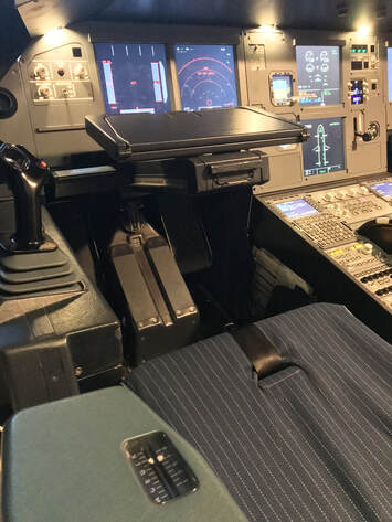
Sitting Comfortably?A comfortable and correct seating position is an important aspect of flying the A320. Ensure that you take the time to get comfortable by adjusting your seating position forward/aft and up/down.
You can find out more about establishing the correct seating position and why it is so important in this Airbus Safety First document here. Flight ControlsSidestick and handling
The sidestick is used to provide control inputs into the pitch and roll axes of the aircraft. The response of the aircraft to these inputs, however, is modulated by flight control algorithms and is dependent upon various characteristics of the current aircraft and flight status. |
Roll commands
The side stick left/right input commands roll rate with the magnitude of the roll rate proportional to the sidestick deflection angle. Crucially when the side stick is in the neutral position the commanded roll rate is 0°/s and the aircraft will thus maintain the bank angle at the time the sidestick was released.
When establishing a turn, the pilot deflects the sidestick to achieve the required roll rate. When the desired bank angle is achieved the pilot releases roll pressure to the side stick and the aircraft will hold the bank angle.
Maximum sidestick deflection orders a maximum roll rate of 15°/s.
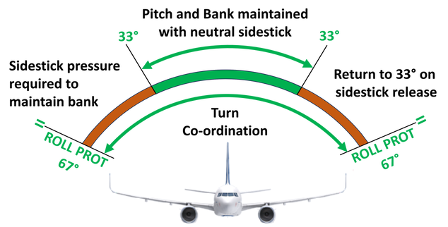
Beyond a bank angle of 33° roll angle is not automatically maintained and the pilot must actively apply non-zero input to the sidestick in order to maintain the desired bank angle. If the sidestick is released the aircraft will automatically roll back to 33°
The pilot can roll the aircraft up to a bank angle limit of 67°. This limit is Roll Protection and is imposed by the flight control computers when operating in the Normal Law flight control law.
Pitch commands
In Normal Law side stick fwd/aft input commands an increase or decrease in g-load with the magnitude of the load rate proportional to the sidestick deflection angle. Crucially when the side stick is in the neutral position the commanded g-load is +1g and the aircraft will hold the pitch angle at the time the sidestick was released.
In Normal Law side stick fwd/aft input commands an increase or decrease in g-load with the magnitude of the load rate proportional to the sidestick deflection angle. Crucially when the side stick is in the neutral position the commanded g-load is +1g and the aircraft will hold the pitch angle at the time the sidestick was released.
Rudder Pedals
Rudder pedals are used to provide directional yaw control of the aircraft. They are primarily used on the ground for steering and maintaining runway centreline during the take-off and landing roll. Automatic turn co-ordination is provided during flight so the rudder pedals are not normally manually operated. In the event of significant flight asymmetry or side-slip then manual rudder operation is required.
Rudder pedals are used to provide directional yaw control of the aircraft. They are primarily used on the ground for steering and maintaining runway centreline during the take-off and landing roll. Automatic turn co-ordination is provided during flight so the rudder pedals are not normally manually operated. In the event of significant flight asymmetry or side-slip then manual rudder operation is required.
Instruments and indications
|
Electronic Flight Instrumentation System (EFIS) Control Panel
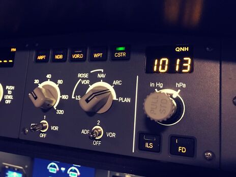
The EFIS control panel enables the pilot to set their respective PFD and ND instrumentation configuration. The panel provide control over the setting, range and content displayed on the Navigation Display (ND) as well as landing system information on the Primary Flight Display (PFD). It also accommodates the control for setting the barometric pressure on the barometric altimeter on the PFD. |
Primary Flight Display
|
Primary Flight Display (PFD)
|
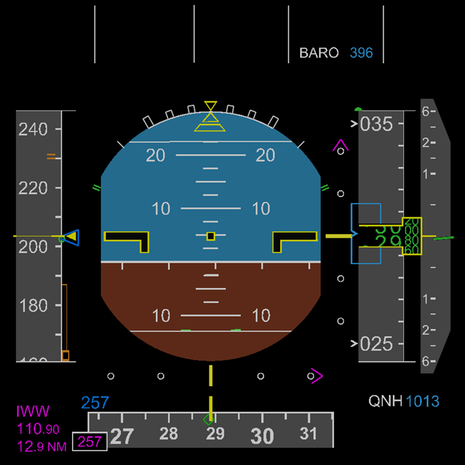
The PFD provides the following flight information:
The PFD also provides the following flight envelope performance and navigation indications:
|
- ILS localiser and glideslope information.
- Localiser front course.
- FMGS computer vertical profile.
- Flight Path Vector (FPV)
Navigation Display
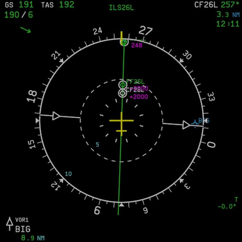
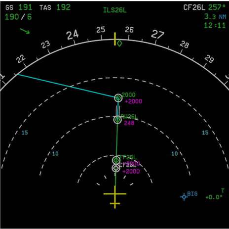
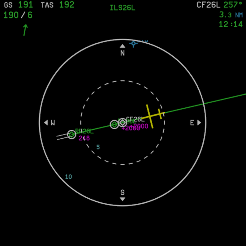
The ND provides navigation information from a top-down view. with several selectable modes and display settings it enables the pilot to maintain and enhance situational awareness of the flight environment and navigation performance.
The ND has the following selectable modes:
The ND has the following selectable modes:
ROSE Modes display a full 360 plan view of the navigation environment:
|
NAV Mode:
Display surrounding navigation waypoints, navaids constraints and other flight plan artifacts. |
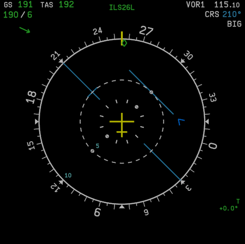
VOR Mode:
Displays a conventional Horizontal Situation Indicator which can be set to a VOR navigation aid. |
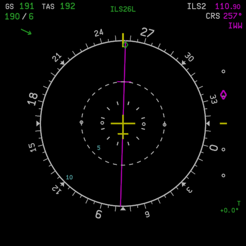
LS Mode:
Displays a conventional Horizontal Situation Indicator with glideslope presenting ILS information for the currently tuned navaid. |
ECAM Engine/Warning Display (E/WD) and System Display (SD)
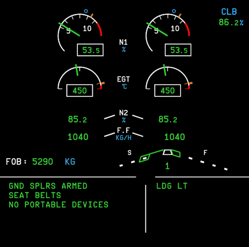
The Electronic Centralised Aircraft Monitoring (ECAM) presents information to the pilots regarding the aircraft's operational, configuration and functional status. The display system is divided between the:
- Engine/Warning Display (E/WD) on the ECAM UPPER display; and
- System Display (SD) on the ECAM LOWER display.
|
Engine/Warning Display
The E/WD is divided into sections and provides the following information: ENGINE Panel:
|
|
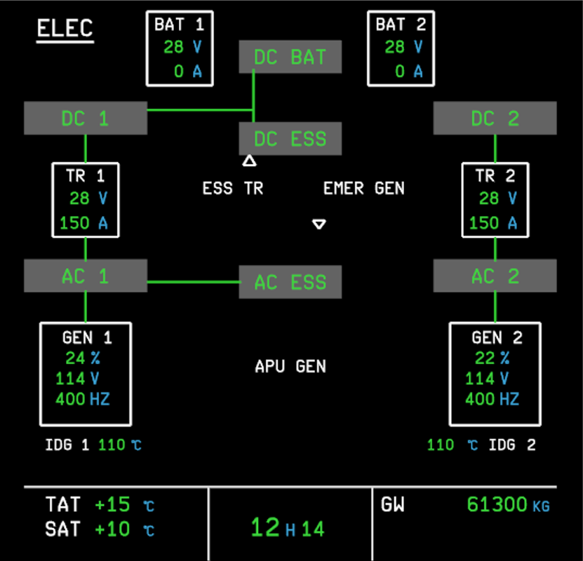
System Display
The SD provides system synoptic summaries of various aircraft systems on independent ECAM SD pages. These pages are displays by manually selecting the respective page on the ECAM selection panel, or automatically according to system logic and prioritisation of indications. The SD pages include:
|
Setting Take-off Thrust
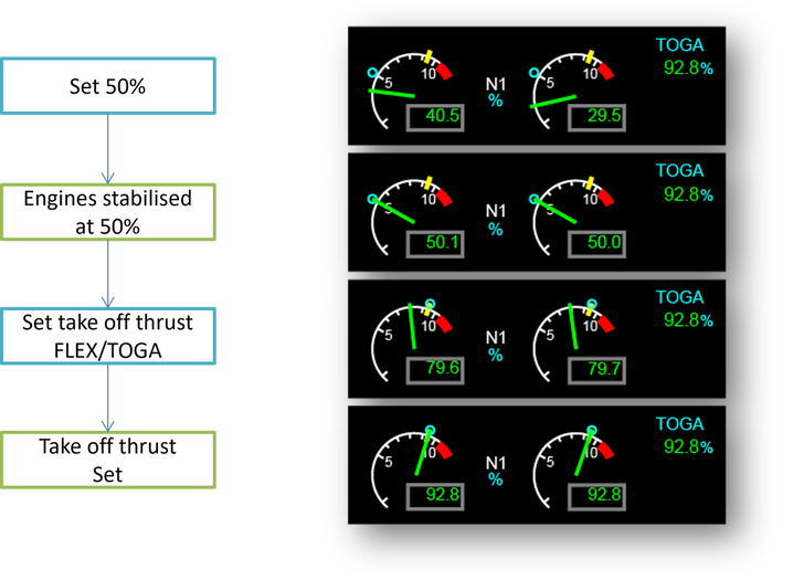
Setting take-off thrust is a two-stage process. Since the engines are completely independent of one another they do not necessarily produce identical thrust profiles during thrust changes.
This means that during particularly large thrust changes - from idle to take-off thrust, that both engines may have a large thrust differential which can cause the aircraft to yaw to one side potentially causing a runway excursion. For this reason, take-off thrust is set with an intermediate pause to allow the engines to stabilise to the same setting before full take-off thrust is set.
This is performed by smoothly advancing the take off thrust setting to 50% and allowing the thrust setting to stabilise. Once stablised the thrust levers may be moved forward into the required take-off thrust position.
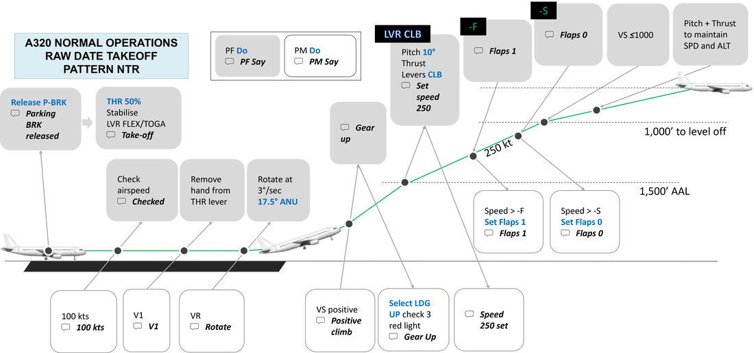
RAW DATA TAKE-OFF
A raw data take-off makes use of primary flight information to control the performance and trajectory of the aircraft. It is normally performed with the Flight Directors off from Thrust Reduction/Acceleration but can also be performed with Flight Directors off from commencing the take-off roll.
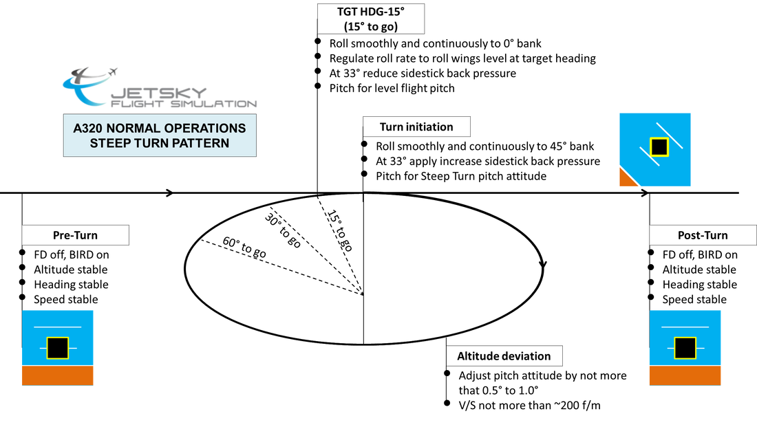
Steep Turns
Steep turn manoeuvres are performed in manual flight with or without FPV guidance. FD bars do not provide steep turn guidance. They are not usually performed under normal operations.
The manoeuvre execution is identical for both left-and-right hand turn directions.
- Begin with the aircraft in straight an level flight at constant speed.
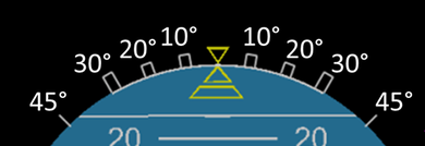
- Note the level flight pitch attitude (at ~5,000 MSL, 25o kts and GW ~55,000kg this will be approximately 2-3° ANU.
- Initate the turn by rolling smoothly and continuously to the 45° bank angle.
- As the aircraft rolls through 33° scan the VSI and, if available, the bird. Auto-pitch trim is inhibited beyond 33° bank and the pilot should apply a small amount of back pressure to the sidestick to maintain level flight. Apply a slight increase in thrust to maintain constant speed.
- When establish in the turn and level flight note the pitch attitude and maintain the necessary sidestick pressure to hold the required pitch and roll angles. The pitch attitude for the turn will be approximately 1°-2° higher than for level flight but it can vary according aircraft weight, airspeed, altitude and temperature.
Little to no sidestick position changes should be required to hold the turn attitude,
Maintain the target airspeed with minimal thrust changes. - Correct altitude deviations will minimal pitch adjustments (<1°) and vertical spesds of not more than 100 – 200 fpm.
- Commence the rollout from the turn with a leading heading of 15° to10°
- Roll smoothly and continuously to wings level. As the aircraft rolls through 33° of bank, apply release the aft sidestick pressure and pitch for the level flight pitch attitude. Apply a slight thrust reduction and adjust as necessary on the rollout to maintain the target airspeed.
|
Level flight prior to the turn
|
Reference pitch during the turn
|
Level flight pitch attitude after turn
|
Note during the early stages of practising steep turn manoeuvres and due to physiological anatomy, the pilot may find that a turn in the direction that requires the sidestick to be pulled inwards towards the body is easier to manage than deflecting the sidestick away from the body. I.e. in the right hand seat, with sidestick in the right hand, it may be easier to control left hand roll than right hand roll. Conversely in the left hand seat, with sidestick in the left hand, it may be easier to control right hand roll than left hand roll.
STEEP TURN MANOUVRE PROFILE
APPROACH PREPARATION
When you are setting up for an approach it's important to start planning ahead as to how you intend to execute the manoeuvring and aircraft handling whilst maintaining safe navigation performance.
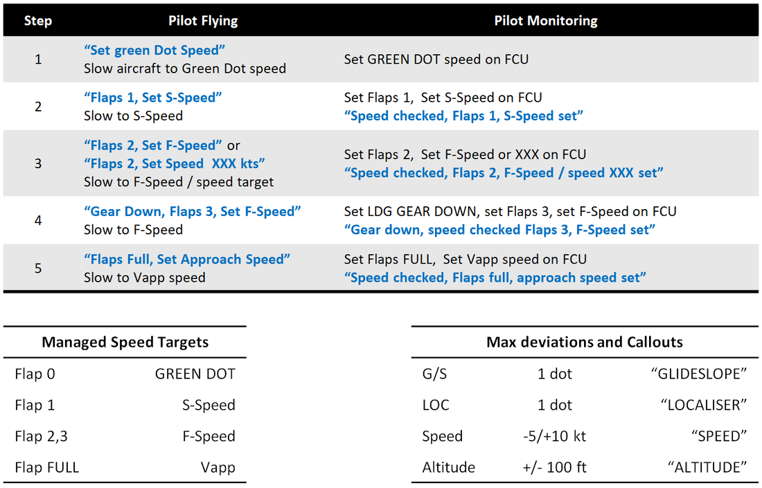
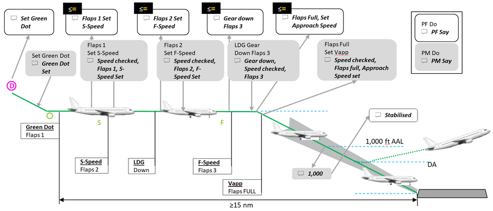
CONFIGURATION CALLOUTS
All images, descriptions and instructions Copyright © 2024 JetSky Flight Simulation.
APPROACH MethoDs
Approached are typically by one of two methods:
- Decelerated Approach
- Early-Stabilised Approach
Decelerated Approach
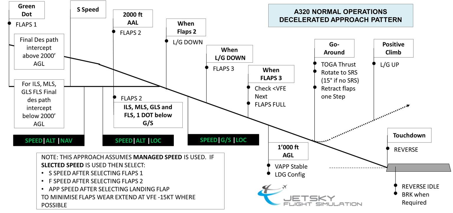
This technique is flown by maintaining a high speed up to, and possibly beyond glideslope capture before executing the majority of the configuration and speed changes
It's typical to arrive at the FAP in either Flap 1 or Flap 2 at around 180 kt. at which time further and continuous flap selection all the way to FULL with gear down and slowing to approach speed should be completed before the approach stabilisation gate at 1,000 ft.
Note that selecting Flap 1 in flight does not extend the flaps so it is advisable to slow to at or below Flap 2 VFE in preparation for extending flaps to commence further deceleration.
Suggested criteria are by 1` nm to the FAP:
- Speed ~180 kt or below VFE-next whichever is lower.
- Flap 1
Early-STABILISED APPROACH
This technique is flown by slowing the aircraft and configuring with sufficient time/distance to stabilise the aircraft in or near the final approach configuration at or close to the final approach speed prior to the Final Approach Point or glideslope intercept.
Suggested criteria are by 1` nm to the FAP:
Suggested criteria are by 1` nm to the FAP:
- F-Speed.
- Flap 3.
- Gear down
- Spoilers armed.
FPA-GUIDED APPROACH (LOC/TRK)
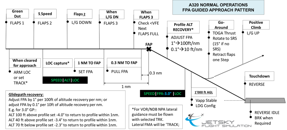
A FPA-guided approach is a non-precision approach using the control of the trajectory flight path angle (FPA)in order to maintain a prescribed glidepath.
The A320 enables the pilot to directly control the FPA and thus make real-time intuitive adjustments to maintain the glidepath in accordance with relevant altitude/distance checkpoints.
The A320 enables the pilot to directly control the FPA and thus make real-time intuitive adjustments to maintain the glidepath in accordance with relevant altitude/distance checkpoints.
Jetsky Training and Operations ManUal
Summary Supplements
|
JTOM - SSC - Manoeuvre Profiles
|
| ||||||

